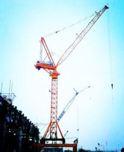
A tower crane load chart shows how lifting capacity changes with working radius and crane configuration. For precast concrete, selection starts with the weight of each lift and the radius at which it must be handled. Maximum crane tonnage alone cannot establish suitability. A lighter panel placed farther from the mast can be more demanding than a heavier component lifted nearby.
The most useful purchasing document is a component schedule linked to the site plan. It allows suppliers to compare the proposed crane configuration against actual lifts, including unloading, movement and final placement. This also helps identify whether a revised crane position could solve a reach problem before equipment is ordered.
Build a Precast Component and Rigging Schedule
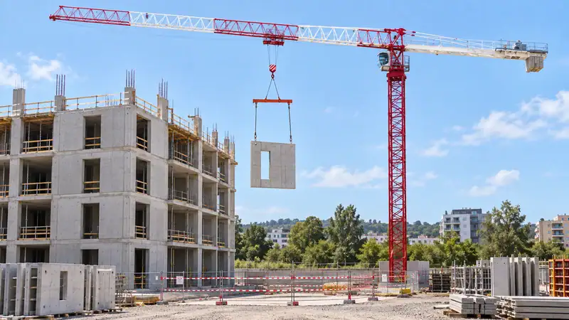
List the precast elements by type and identify the heaviest or most demanding examples. Include panels, beams, stairs, slabs and any special units in the crane’s scope. Record verified weights from the component supplier rather than estimating from appearance.
Add dimensions, lifting points, delivery orientation and final position. These details influence rigging, available clearance and the way the element reaches its installed orientation. Lifting inserts and handling methods must follow the precast designer’s requirements.
Include temporary attachments or equipment that travel with the component. Record the weight of lifting beams, slings, clutches and other rigging. Follow the crane manufacturer’s load-chart instructions when accounting for hook blocks and other deductions, so items are neither omitted nor counted twice.
Calculate Tower Crane Working Radius for Every Lift
Working radius is the horizontal distance from the crane’s center of rotation to the load line. It is not the distance from the building edge or the length of rope below the hook.
Measure the radius at the delivery vehicle, storage location and installation point. Review the proposed travel path as well. The most demanding position can occur before final placement if the route passes around an obstruction or the load must be collected farther away.
Mark the crane position on a current site plan. If the mast location changes, revise the radius checks. Even a relatively small shift can alter which lifts fall near the limits of the proposed configuration.
IHURMO’s tower crane selection guide covers general load and site requirements. For precast work, those checks need to be attached to individual components and handling positions.

Create a Lift Schedule for Load Chart Review
The following is an illustrative planning example. It is not an approved lifting plan or a statement of any IHURMO crane’s capacity. Other deductions required by the selected crane’s chart must also be applied.
| Example component | Component mass | Listed rigging mass | Combined mass before other chart deductions | Maximum planned radius |
| Wall panel A | 2,400 kg | 350 kg | 2,750 kg | 32 m |
| Beam B | 3,500 kg | 450 kg | 3,950 kg | 24 m |
| Stair unit C | 2,900 kg | 400 kg | 3,300 kg | 38 m |
Beam B has the highest combined mass, but Stair C reaches farther. Every row requires a separate check against the relevant chart. Selecting a crane solely because its maximum rating exceeds 3,950 kg would leave the radius question unanswered.
For a real project, add component dimensions, pick and placement coordinates, hook height and any special handling requirements. Keep the schedule tied to the same drawing revision used for the crane layout.
How to Read a Tower Crane Load Chart
Request the tower crane load chart for the exact crane model, jib arrangement and operating configuration being quoted. Check the applicable reeving, meaning the arrangement of rope parts supporting the hook, together with any chart conditions or restrictions.
A shorter jib configuration may have a different capacity profile from a longer one. Additional reach is useful only when the crane can handle the required load at that reach. Manufacturer charts can also include different operating modes, which must not be treated as interchangeable.
Ask the supplier to identify the chart reference used for each critical lift. The crane and lifting teams should confirm all required allowances under the manufacturer’s instructions and project requirements. A general percentage added to the load cannot replace that review.
Where a lift does not fit, assess the full set of options: another crane configuration, a different mast position, revised unloading or storage areas, or an approved change to the handling sequence. Changes to the precast component itself require its designer’s involvement.
Check Hook Height and Clearance above the Component
Hook height must accommodate the building, the component and the rigging arrangement. A tall panel or lifting beam can require substantial space above the final installation level. The crane team must also account for the manufacturer’s operating clearances.
Review the route into position, not just the final height. Nearby structures, temporary works and other cranes may restrict movement. Delivery orientation matters because a component that must be turned or tilted needs a suitable handling method and clearance.
Long reach and adequate capacity do not resolve these issues automatically. Put the critical lift geometry into the supplier review before comparing prices.
Account for Wind and Precast Placement Demands
Large precast panels can present substantial surface area to wind. Weight alone therefore does not describe the whole lifting condition. The lifting plan must consider component geometry, wind exposure and the limits applicable to the crane and lift.
Do not adopt one generic wind-speed threshold for every panel. Follow the crane manufacturer’s guidance and the project lifting assessment. Unusual shapes or exposed positions may require additional review.
Placement also involves time for alignment, connection and temporary stability. The erection team must confirm when the component is secured and the crane can release the load. Those requirements affect crane occupancy and the achievable installation rate.
Compare Tower Crane Productivity and Supply Scope
Estimate the planned number of lifts and the time needed for rigging, movement, alignment and release. Coordinate delivery slots and storage areas with the erection sequence. A crane can meet the capacity requirement yet become a production bottleneck if it also serves competing site activities.
Review hoisting performance at the relevant loads and the handling control needed for placement. Compare these requirements alongside the equipment price. The fastest unloaded hoist speed is not a useful measure of the entire precast cycle.
Require quotations to identify the model, jib configuration, tower arrangement, hook height and load-chart reference. Clarify foundation interfaces, ties, erection support, electrical supply, documentation and spare parts. Distinguish equipment supply from services provided by the local installation and lifting teams.
Submit Precast Lift Data and Request the Correct Load Chart
Send IHURMO the component schedule, site plan, proposed crane position and required hook heights. Include rigging information, critical radii and the erection sequence. Request suitable tower crane configurations with the corresponding load charts. Contact IHURMO for a quotation based on the project’s actual lifts, so technical suitability and supply scope can be compared together.
Tower Crane Load Chart FAQs
Is the heaviest component always the governing lift?
No. Radius, rigging, chart conditions and handling geometry can make another component more demanding. Check each critical combination of load and position.
Can moving the delivery area improve crane selection?
It may reduce the pickup radius or simplify the route. The revised location must still fit site logistics and the approved lifting plan. Recheck every affected lift after the change.